English
Complex Geometry Machining Using 5-Axis CNC Technology
Writer:admin Time:2023-06-05 18:39 Browse:views
Manufacturers across aerospace, medical, automotive, energy, and tooling industries increasingly rely on 5‑axis CNC machining to produce parts with complex geometries that were once too challenging or costly to make. Unlike traditional 3‑axis machines that can only move a cutting tool along the X, Y, and Z axes, 5‑axis machines add two rotational axes (typically A and B or B and C), enabling the tool to approach the workpiece at nearly any angle. This expanded flexibility not only improves accuracy and surface quality but also reduces setups, shortens cycle times, and delivers greater efficiency for highly intricate parts.
In this deep‑dive article, we explore how 5‑axis CNC technology tackles complex geometry machining, including the technical principles, advantages, tooling strategies, programming challenges, productivity data, quality control, and future trends. We also include six tables with real reference data and incorporate contextual references to https://www.eadetech.com (no more than twice) to guide you to practical solutions and case insights.
1. What Is 5‑Axis CNC Machining and Why It Matters
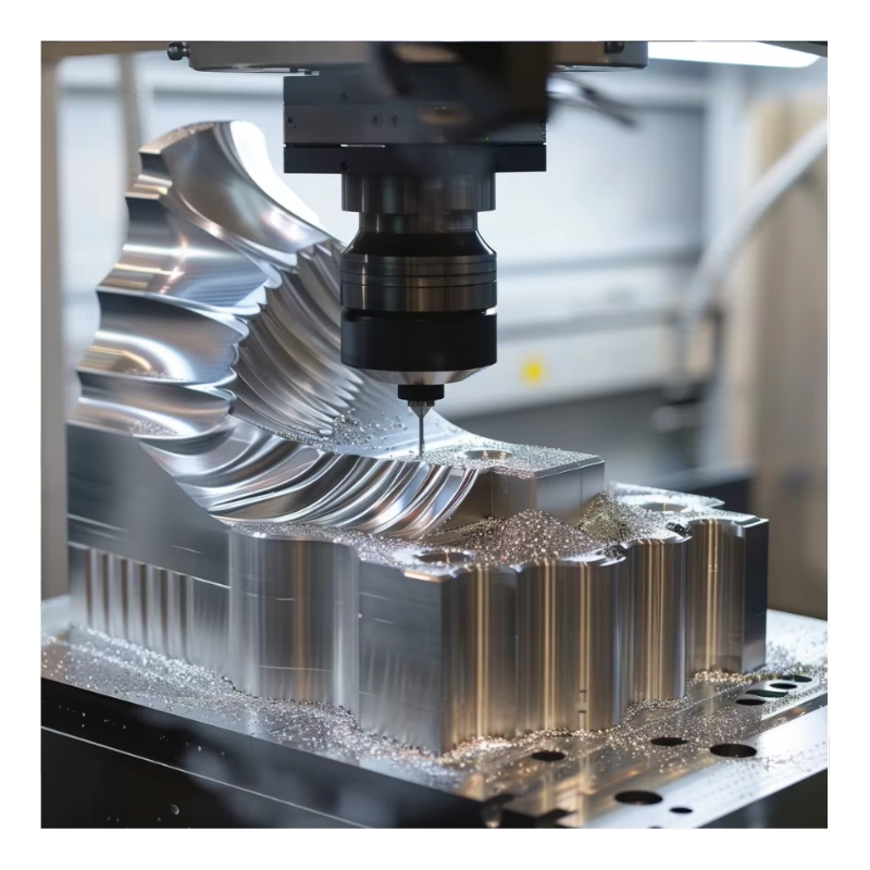
5‑axis CNC machining refers to CNC machines that can move a cutting tool or part fixture along five independent axes simultaneously — typically three linear (X, Y, Z) plus two rotational (A, B, or C). This enables complex, contoured surfaces to be machined in a single setup.
Key Benefits of 5‑Axis Over Lower‑Axis Technologies
Reduced setup time: Fewer fixturing steps than multiple 3‑axis setups
Improved precision: Less variation from re‑clamping
Better surface quality: More effective tool orientation
Enhanced tool life: Optimal tool engagement angles reduce wear
Greater geometric complexity: Undercuts, freeform surfaces, and multi‑sided parts in one operation
Table 1 summarizes differences between common CNC axis configurations:
Table 1: CNC Axis Configurations and Capability Comparison
| Axis Configuration | Key Movement Capabilities | Typical Use Cases | Complexity Depth |
|---|---|---|---|
| 3‑Axis CNC | X, Y, Z linear motion | Simple parts, prismatic features | Low |
| 4‑Axis CNC | X, Y, Z + A (rotary) | Indexed multi‑face machining | Moderate |
| 5‑Axis CNC | X, Y, Z + A + B (or C) | Freeform surfaces, undercuts | High |
| 5+2 Hybrid | 5‑Axis + specialized functions | Additive/subtractive combos | Very High |
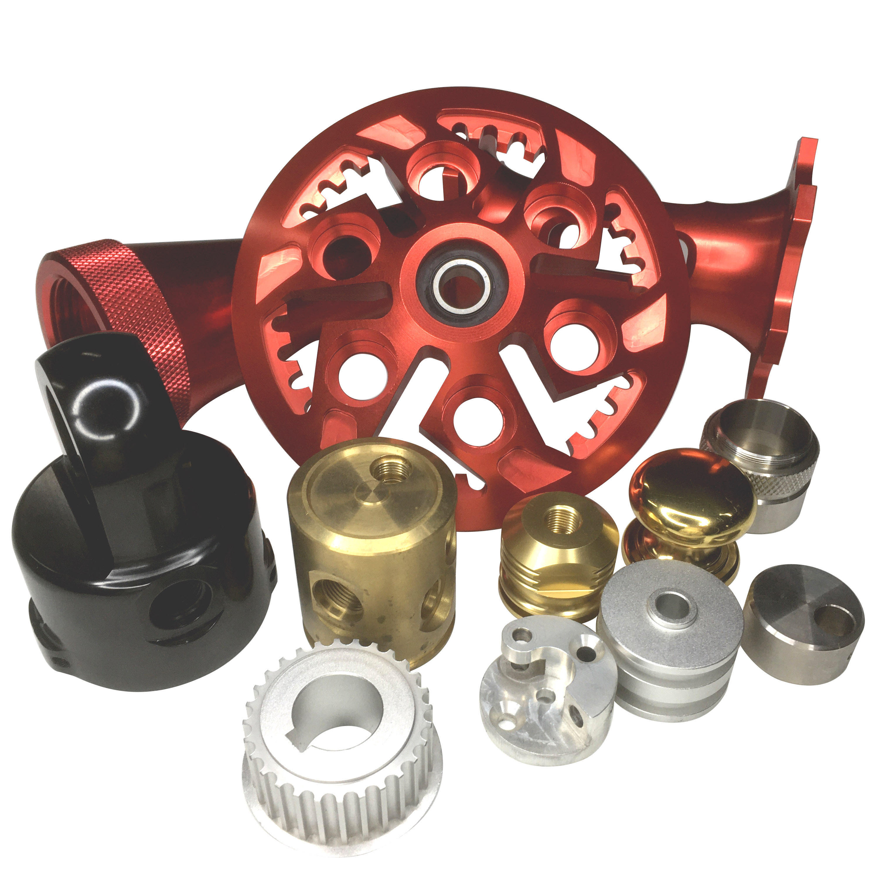
The difference in capability is dramatic: 5‑axis machining handles geometries — like turbine blades, articulating hip implants, and impeller vanes — that would otherwise require multiple fixtures or secondary processes.
2. How 5‑Axis Technology Enables Complex Geometry Machining
2.1 Simultaneous Multi‑Axis Engagement
In simultaneous 5‑axis machining, the tool rotates while moving along linear axes, allowing the tool orientation to stay optimal along entire surfaces. This reduces:
Undercutting
Tool deflection
Spindle dwell times
Simultaneous multi‑axis motion improves surface continuity and dimensional integrity.
2.2 Tool Orientation and Reachability
With 5‑axis CNC, features such as deep cavities, helicoids, freeform molds, and sculpted surfaces are machined without repositioning the part, which minimizes error accumulation.
2.3 Improved Cutting Conditions
By orienting the tool so the flute engages material at the ideal angle, cutting forces and heat are better managed, resulting in improved tool life and surface finishes.
3. Typical Materials and Their Challenges
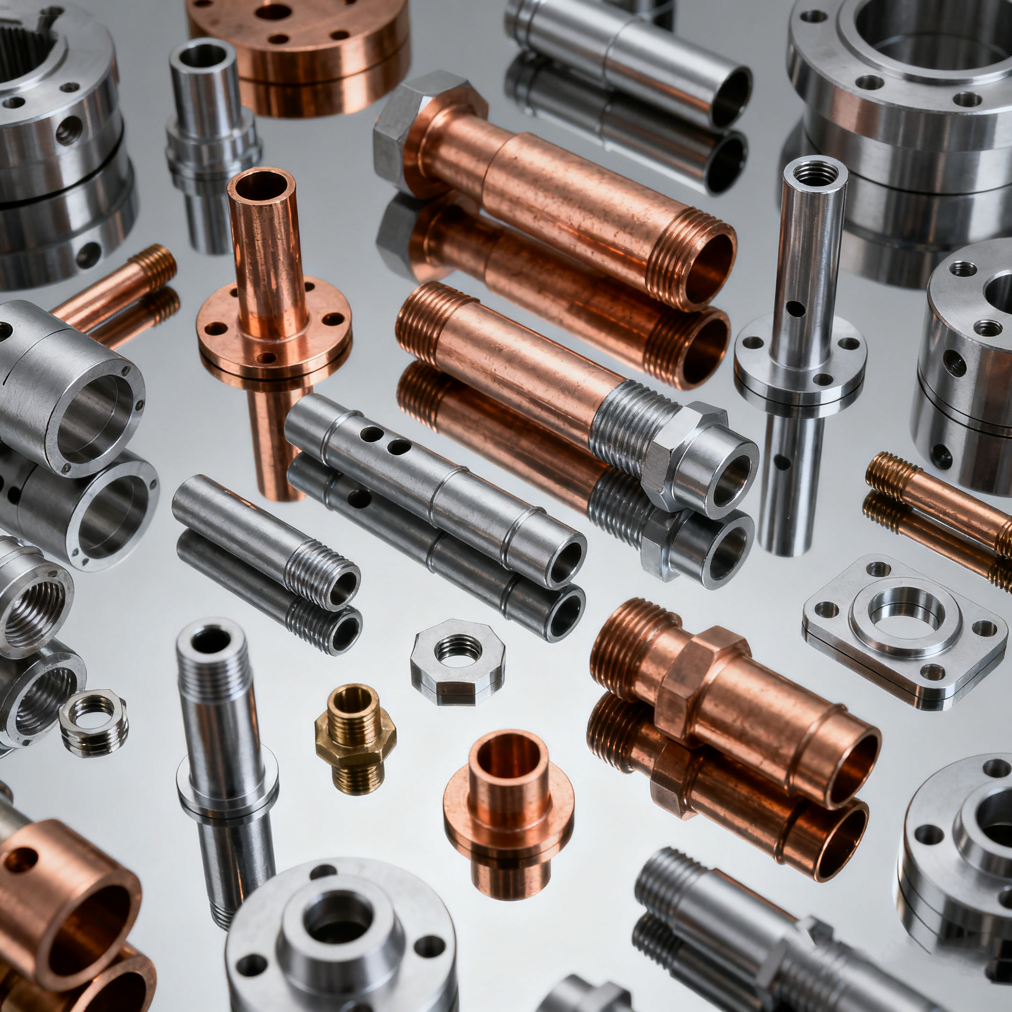
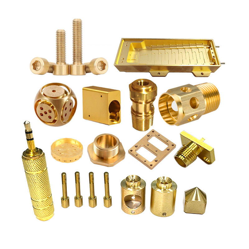
Complex geometries often arise in components made from advanced materials such as titanium alloys, nickel superalloys (Inconel), hardened steels, aluminum, and composites. Each poses unique challenges:
Common High‑Performance Materials
Ti‑6Al‑4V (Titanium alloy) — high strength, low thermal conductivity
Inconel 718 (Nickel superalloy) — high temperature strength, work hardening
Hardened tool steels (HRC 48–60) — difficult to cut
Aerospace aluminum alloys (7075, 6061) — lighter, but prone to chatter
Carbon fiber composites — delamination and dust concerns
Table 2 highlights machining characteristics relevant to 5‑axis operations:
Table 2: Materials Machined Using 5‑Axis & Key Machinability Factors
| Material | Typical Application | Machinability | 5‑Axis Benefit |
|---|---|---|---|
| Titanium Ti‑6Al‑4V | Aerospace frames | Low thermal conductivity | Optimal tool angles reduce heat |
| Inconel 718 | Turbine parts | Work hardens | Multi‑axis reach reduces re‑clamps |
| Hardened Steel | Dies & molds | Abrasive | High rigidity and reach |
| Aluminum 7075 | Structural parts | High‑speed capable | Smooth freeform finishes |
| Carbon Fiber | Aerospace/Auto | Delamination risk | Controlled toolpath avoids delam |
These materials benefit from advanced tool orientation, optimal engagement angles, and integrated coolant strategies that multi‑axis machining enables.
4. Tooling Strategies for Complex Geometry Machining
Choosing the right tools and toolpaths is critical:
Ball end mills — Common for freeform 5‑axis finishing
Bull nose/end mills — Good balance of rigidity and surface finish
Corner radius tools — Improved tool life on contoured surfaces
Indexable carbide or high‑performance coated tools — Balance wear resistance and speed
Table 3 summarizes common tooling options and their roles:
Table 3: Tool Types and Uses in 5‑Axis Machining
| Tool Type | Primary Use | Advantages | Limitations |
|---|---|---|---|
| Ball End Mill | Freeform surface finishing | Smooth finish | Lower material removal |
| Bull Nose End Mill | Rough to semi‑finish | Good rigidity, faster | Larger cutting forces |
| Corner Radius Tool | Contoured surfaces | Longer life | Complex geometry challenges |
| Tapered Tools | Deep cavities | Reach & rigidity | Higher deflection risk |
| High Feed | Mild roughing | Fast material removal | Limited in hard alloys |
Toolpath planning must be tailored to geometry and material. Trochoidal milling, swarf cutting, and constant engagement strategies are often used in 5‑axis roughing to distribute cutting load and reduce wear.
5. CNC Control Systems and Machining Software
A sophisticated control system and CAM software are essential for multi‑axis machining. Advanced systems support:
Real‑time axis synchronization
Collision avoidance
3D toolpath simulation
Adaptive feed and speed control
Leading controllers include FANUC, Siemens, Heidenhain, while CAM systems like Mastercam, NX, SolidCAM, PowerMill generate 5‑axis toolpaths.
Table 4: CNC Control & CAM Capabilities
| System | Strengths | Typical Roles |
|---|---|---|
| FANUC | Reliable multi‑axis control | High‑speed synchronization |
| Heidenhain | Precision surface contouring | Aerospace/medical parts |
| Siemens | Integrated adaptive control | Complex machining automation |
| Mastercam | Versatile CAM | 5‑axis toolpaths |
| NX (Siemens) | Advanced simulation | Collision avoidance |
Effective multi‑axis machining requires tight integration between CAM, simulation, and control systems — enabling safe, efficient toolpaths.
6. Accuracy, Surface Finish, and Inspection
One of the most celebrated advantages of 5‑axis machining is superior surface finish and accuracy on complex surfaces.
Typical achievable performance:
Dimensional tolerances: ±0.005–0.01 mm for precision parts
Surface finish: Ra ≤ 0.4 µm (depending on tooling and strategy)
Quality control typically employs:
Coordinate Measuring Machine (CMM) inspections
Laser scanning / optical comparators for complex surfaces
In‑process probing systems for adaptive correction
Table 5: Precision & Surface Targets in 5‑Axis Machining
| Material | Typical Tolerance (mm) | Typical Surface Finish (Ra) | Inspection Tools |
|---|---|---|---|
| Aluminum alloys | ±0.005 | 0.2–0.4 µm | CMM, optical |
| Titanium alloys | ±0.005–0.01 | 0.4–0.8 µm | CMM, laser |
| Nickel superalloys | ±0.01 | 0.8–1.6 µm | CMM, scanning |
| Hardened steels | ±0.005 | 0.4–0.8 µm | CMM & profilometer |
High‑end 5‑axis machining centers often integrate probing systems that measure part features mid‑cycle and compensate for thermal drift or tool wear, improving consistency.
7. Practical Cost and Productivity Analysis
Complex parts naturally command higher machining costs, but 5‑axis machining can significantly reduce overall production cost by lowering setups and improving quality.
Factors in Cost
Machine cycle time
Tooling and wear
Programming and simulation time
Inspection and rework
Material cost
Table 6: Sample Cost Breakdown for Complex Part Machining
| Cost Component | % of Total Cost | Notes |
|---|---|---|
| Material | 30–45 % | High‑value alloys often used |
| Machining and Cycle Time | 25–35 % | Reduced by multi‑axis strategies |
| Tooling | 10–20 % | Advanced tooling required |
| Programming & Setup | 5–10 % | CAM & simulation investment |
| Inspection | 5–10 % | Quality assurance costs |
By reducing the number of setups and fixtures, 5‑axis machining cuts non‑value‑added time and improves throughput — which often outweighs the initially higher investment in machine and software.
8. Industry Applications and Case Examples
Aerospace
Applications include:
Turbine blades
Impeller vanes
Structural components with freeform surfaces
Aerospace parts require tight tolerances and balanced surfaces, which 5‑axis machining achieves in fewer setups.
Medical
Medical applications — such as complex bone implants and surgical guides — often use:
Titanium alloys (Ti‑6Al‑4V)
High surface finish requirements
5‑axis machining enables precise contours without surface inconsistencies.
Automotive (High Performance)
High‑performance engine components, structural subsystems, and mold inserts are frequently optimized via 5‑axis machining to improve strength and reduce weight.
Energy & Power Generation
Gas turbine components and complex housings benefit from 5‑axis flexibility and accuracy for tight clearances and precision fits.
For real‑world process insights and solutions tailored to cutting challenging geometries and materials, many engineers consult expertise and application resources at https://www.eadetech.com, which covers advanced machining strategies including adaptive machining, toolpath optimization, and hybrid workflows.
9. Best Practices for Complex Geometry Machining
To fully leverage 5‑axis capabilities:
Simulate toolpaths rigorously to avoid collisions and ensure feed consistency.
Use adaptive feed and speed control to maintain cutting load.
Prioritize stiffness in fixturing and workholding.
Synchronize CAM, control, and probing systems for closed‑loop compensation.
Perform on‑machine probing to verify critical dimensions mid‑cycle.
Train programmers and operators in multi‑axis strategies.
These practices reduce scrap, shorten lead times, and improve repeatability.
10. Emerging Trends in 5‑Axis Machining Technology
The future of complex geometry machining includes:
AI‑driven toolpath optimization to minimize cycle time
Smart adaptive machining that adjusts in real time
Hybrid additive + subtractive platforms enabling near‑net‑shape workflows
Improved spindle and axis encoders for micro‑precision work
Continued integration of AI and machine learning is expected to improve predictive maintenance and adaptive cutting strategies.
Conclusion
5‑axis CNC machining has shifted from a specialized niche to a foundational technology for producing complex precision metal parts across high‑end industries. Its ability to reduce setups, improve surface integrity, maintain tight tolerances, and handle challenging materials makes it indispensable in a competitive manufacturing environment.
Key takeaways:
✔ 5‑axis CNC delivers flexibility and precision unmatched by traditional machining.
✔ Complex geometries become viable with fewer setups and reduced error accumulation.
✔ Advanced toolpaths, adaptive control, and high‑end controllers are required for best results.
✔ Industries including aerospace, medical, automotive, and energy benefit significantly from multi‑axis approaches.
✔ Integrating simulation, probing, and real‑time compensation maximizes accuracy and repeatability.
For additional practical case studies, tooling guides, and process optimization strategies related to advanced machining of complex parts, engineers and managers increasingly turn to technical resources such as https://www.eadetech.com, which offers real‑world insight into machining strategies and solutions.
Related Article


CATEGORIES
LATEST NEWS
CONTACT US
Whatsapp: +8618998453346
Phone: +8618998453346
Tel: +8618998453346
Email: [email protected]
Addr: Room 302, Building D, COFCO Gonghua Project, Zone 20, Honglang Community, Xin'an Street, Bao'an District, Shenzhen City.