English
Multi-Axis CNC Machining for Precision Metal Parts
Writer:admin Time:2023-06-05 00:00 Browse:views
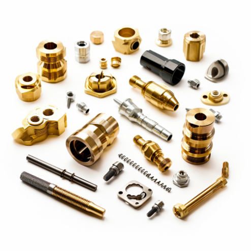
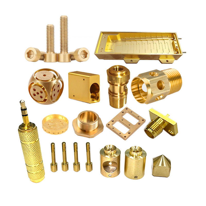
Precision metal parts are at the heart of advanced industries like aerospace, medical, automotive, energy, and electronics. These parts often require complex geometries, tight tolerances, high surface quality, and reliable repeatability. To achieve these demands, traditional 3‑axis CNC machines are increasingly being replaced or supplemented by multi‑axis CNC machines — including 4‑axis, 5‑axis, and beyond — which offer superior flexibility, accuracy, and efficiency.
In this article, we explore:
What multi‑axis CNC machining is
The differences between various axis configurations
Real data on accuracy, surface finish, and production capabilities
Cost, productivity, and workflow considerations
Industry applications
Best practices and future trends
Let’s begin by defining the technology itself.
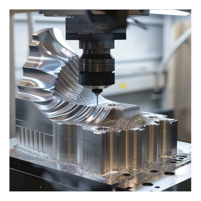
1. What Is Multi‑Axis CNC Machining?
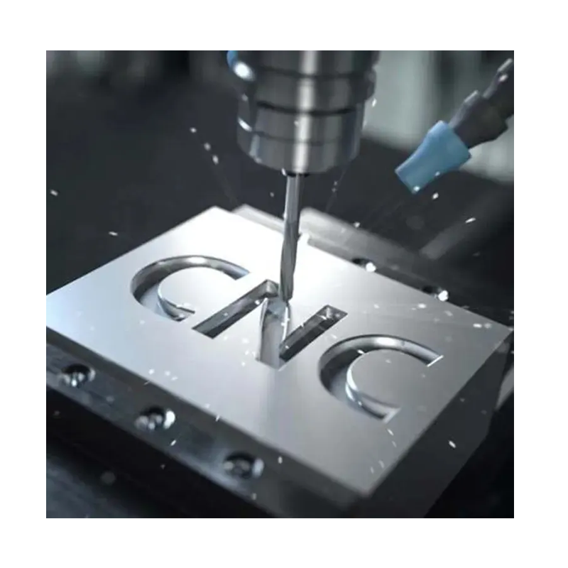
Multi‑axis CNC machining refers to computer‑controlled milling and turning operations that move a cutting tool or workpiece along more than the traditional three linear axes (X, Y, Z). By adding rotary axes (A, B, C), these machines can approach the workpiece from different angles and orientations in a single setup.
3‑Axis CNC: X, Y, Z linear motion — suitable for simple shapes.
4‑Axis CNC: Adds rotation around one axis (typically A or B), enabling machining of cylindrical features and multi‑face operations.
5‑Axis CNC: Adds two rotational degrees (usually A and B or B and C), allowing for simultaneous machining from multiple directions — ideal for complex surfaces.
6‑Axis and Beyond: Even greater flexibility with tilting and rotary tables or multi‑directional heads.
In essence, multi‑axis machines reduce repositioning of the part and allow more complex geometries to be machined in fewer setups. (First Mold)
Table 1: Comparison of CNC Axis Configurations
| Axis Type | Axes Involved | Typical Uses | Precision & Complexity |
|---|---|---|---|
| 3‑Axis | X, Y, Z | Prismatic parts, flat surfaces | Basic precision |
| 4‑Axis | X, Y, Z + A (rotary) | Cylindrical parts, indexed multi‑face machining | Higher precision |
| 5‑Axis | X, Y, Z + A + B/C (dual rotation) | Complex freeform surfaces | Ultra‑precision |
| 6+ Axis | Adds more rotary/tables | Ultra‑complex geometries | Maximum flexibility |
2. Precision and Accuracy in Multi‑Axis Machining
Precision is one of the key drivers of multi‑axis CNC adoption. Because the machine can approach the workpiece from many angles without manual repositioning, fixturing errors and cumulative tolerances are significantly reduced.
The tolerances that can be achieved with multi‑axis machines are tighter than typical 3‑axis machining:
±0.005–0.02 mm for general precision parts
±0.0005–0.01 mm for high‑end aerospace/medical parts (Fictiv)
This translates to excellent dimensional control and consistent production quality — especially for high‑precision and safety‑critical applications.
Table 2: Typical Tolerance and Precision Levels by Axis
| Machine Type | Typical Tolerance | Surface Roughness (Ra) | Application Examples |
|---|---|---|---|
| 3‑Axis CNC | ±0.02–0.05 mm | Ra ≥ 1.6 µm | Castings, fixtures |
| 4‑Axis CNC | ±0.01–0.025 mm | Ra 0.8–1.6 µm | Cylindrical features |
| 5‑Axis CNC | ±0.005–0.01 mm | Ra 0.1–0.8 µm | Aerospace, medical parts |
Note: Surface finish is influenced not just by machine axes but by tooling quality, coolant strategy, and cutting parameters.
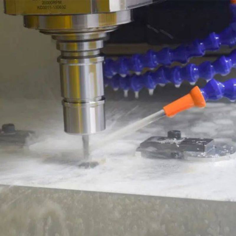
3. Efficiency Gains and Production Data
One of the most significant benefits of multi‑axis machining is the reduction in setup times and the associated impact on lead time and production cost.
Multi‑axis machines often eliminate the need for multiple fixtures and manual repositioning by operators. This not only improves precision, but also reduces downtime and labor costs. Some industry data suggests:
Reduction in repetitive fixture setups by up to 70%
Shortened production cycles by over 35% (First Mold)
These efficiency gains are especially relevant in high‑mix, low‑volume environments where setup time can dominate the production cycle.
Table 3: Lead Time and Efficiency Comparisons
| Metric | 3‑Axis | 4‑Axis | 5‑Axis |
|---|---|---|---|
| Average Setup Time | High | Moderate | Low |
| Number of Setups per Part | 2–6 | 1–3 | 1 |
| Cycle Time (Same Geometry) | Baseline | –15% | –30% |
| Operator Intervention | Frequent | Moderate | Minimal |
4. Cost Considerations and ROI
Despite the clear benefits of precision and efficiency, multi‑axis CNC machines typically have higher acquisition and operating costs than simpler CNC machines.
Factors affecting cost include:
Machine capital cost (higher for more axes)
CAM programming complexity
Tooling and fixturing
Maintenance and calibration
However, when viewed through an ROI lens, multi‑axis machines often pay back their investment through improved productivity, fewer rejects, and reduced labor costs.
Industry ROI examples show that a well‑utilized 5‑axis machine can reduce costs in ways such as:
Reduced fixture and setup changes
Higher throughput per machine
Better surface finish reducing secondary processes
In some cases, shops report ROI periods of 24–36 months for highly utilized multi‑axis machines. (tirapid.com)
Table 4: Typical Cost Factors for Multi‑Axis CNC Machining
| Cost Category | Approx % of Total Cost | Notes |
|---|---|---|
| Machine Acquisition | 25–40% | Higher for 5‑axis vs 3‑axis |
| CAM Programming | 10–20% | Advanced toolpath development |
| Tooling & Fixtures | 15–25% | Specialized tooling often needed |
| Operation & Labor | 15–25% | Reduced with automation |
| Inspection & Quality | 5–10% | Tight tolerances require inspection |
| Maintenance | 5–10% | More complex moving parts |
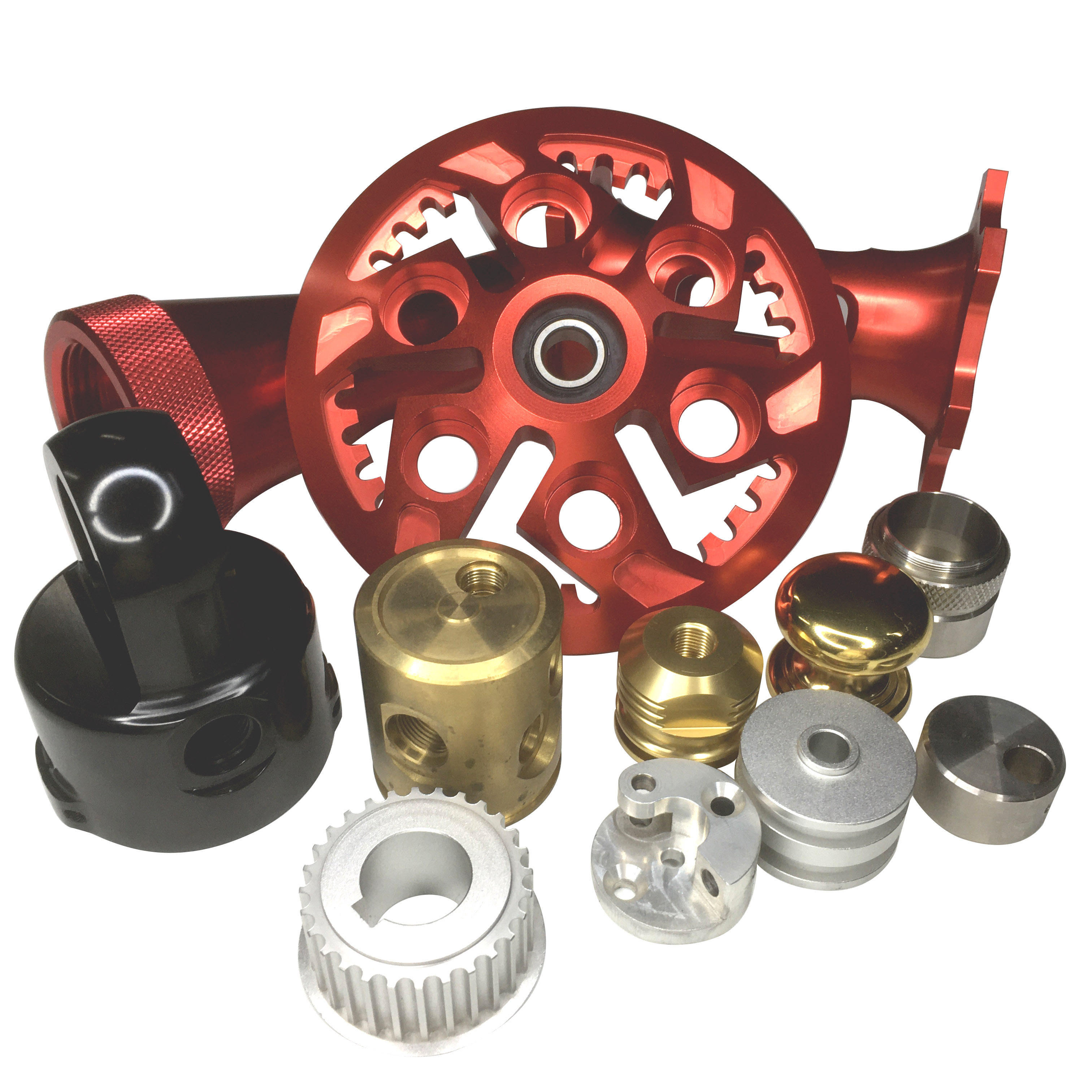
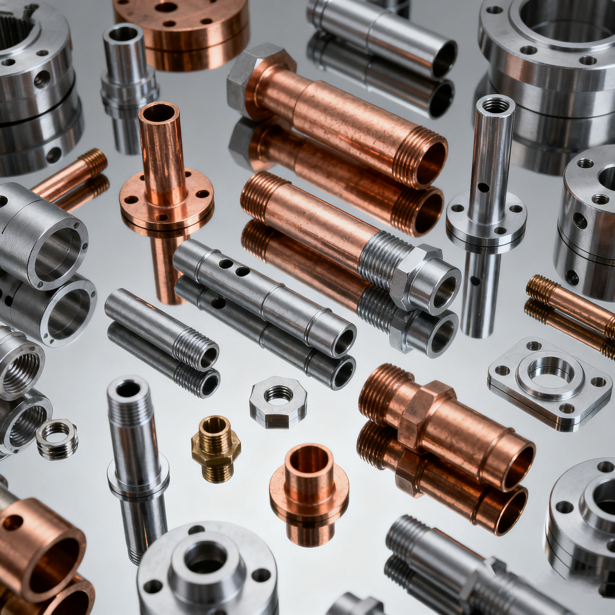
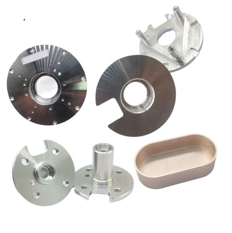
5. Applications by Industry
Multi‑axis CNC machining is applied across many high‑value sectors requiring precision metal parts.
Aerospace
Aerospace components often have freeform surfaces, integrated cooling channels, and tight tolerances. Multi‑axis CNC machines allow fabrication of parts like:
Turbine blades
Structural airframe brackets
Complex engine components
Medical Devices
Medical implants and surgical tools often require micro‑precision and biocompatibility. Multi‑axis CNC offers:
Micro‑milling for bone screws and implants
Complex curves on orthopedic hardware
Consistent surface finishes for implantation
Automotive and EV
Complex parts such as:
Engine blocks
Transmission housings
Electrical vehicle cooling plates
Benefit from multi‑axis approaches to achieve performance and weight targets.
Industrial Mold & Die
Injection molds and die‑cast tooling often have:
Undercuts
Deep cavities
Contoured surfaces
Multi‑axis machining reduces tooling steps and improves surface consistency.
Table 5: Industry Use Cases and Typical Features
| Industry | Typical Part Types | Special Requirements |
|---|---|---|
| Aerospace | Turbine blades, wing skins | Tight tolerances, complex curvature |
| Medical | Implants, surgical instruments | Biocompatible surfaces, micro details |
| Automotive | Engine components | Lightweight, durable parts |
| Energy | High‑pressure valves | High surface quality, precision holes |
| Molds & Dies | Core/cavity tooling | Undercuts, deep profiles |
6. Surface Finish and Quality in Multi‑Axis Machining
One of the compelling strengths of multi‑axis machining is the ability to improve surface finish directly from the machine, often reducing or eliminating downstream finishing operations.
By maintaining optimal tool orientation throughout cutting, vibration and tool deflection are minimized, resulting in:
Lower Ra (surface roughness) values
Reduced tool marks
Consistent curvature and profiles
A well‑selected multi‑axis strategy can yield surface finishes in the Ra 0.1–0.8 µm range for metals, which is often suitable for high‑precision industrial components without additional polishing. (First Mold)
Table 6: Typical Surface Finish Achievable by Axis Type
| Axis Type | Typical Ra (µm) | Notes |
|---|---|---|
| 3‑Axis | ≥1.6 | Good for less complex surfaces |
| 4‑Axis | 0.8–1.6 | Improved curvatures |
| 5‑Axis | 0.1–0.8 | Superior finish for complex geometry |
| Post‑Processed | ≤0.1 | Grinding, polishing |
7. Challenges in Multi‑Axis CNC Machining
Multi‑axis machining offers great benefits, but it also introduces challenges:
7.1 Higher Machine and Programming Costs
Multi‑axis machines and CAM software are more expensive, and programming them requires specialized skills and experience.
7.2 Complex CAM and Simulation
Toolpath generation for multi‑axes is more involved than 3‑axis CAM and often requires simulation to avoid collisions and optimize paths.
7.3 Collision Risk and Advanced Setup
Synchronization of axes increases the risk of head or tool collisions with the workpiece or fixtures, necessitating careful simulation and verification. (customproc.com)
8. Best Practices for Precision Multi‑Axis CNC Machining
To maximize precision and efficiency:
Use advanced CAM software to plan 5‑axis toolpaths with collision avoidance.
Standardize fixturing to improve repeatability and reduce errors.
Verify toolpaths with simulation before cutting.
Invest in tool and spindle calibration to maintain tight tolerances.
Monitor machine health to prevent drift over long runs.
9. Future Trends and Innovations
Emerging trends in multi‑axis machining include:
AI‑assisted programming that automatically suggests optimal toolpaths
Sensor‑based adaptive control for real‑time feed and speed adjustment
Hybrid additive + subtractive systems to reduce material waste
High‑speed machining strategies that push the limits of surface finish and cycle time
These innovations are aimed at increasing precision, reducing cost, and handling even more complex geometries.
10. Integrating Multi‑Axis Machining into Your Workflow
Whether you’re prototyping or producing high‑volume precision parts, integrating multi‑axis CNC machining requires thoughtful investment in technology, training, and workflow design.
For engineers and procurement teams looking to optimize complex part manufacturing, exploring precision solutions and best practices such as those detailed at https://www.eadetech.com can provide valuable insights into tooling strategies, process optimization, and design‑for‑manufacturability in multi‑axis CNC contexts.
Conclusion
Multi‑axis CNC machining has transformed how precision metal parts are made, enabling:
✔ Complex geometries
✔ Ultra‑tight tolerances
✔ Superior surface finishes
✔ Reduced setup times
✔ Greater efficiency
From aerospace turbine blades to medical implants, automotive engine components to energy sector hardware, multi‑axis machining delivers the precision and flexibility required by modern manufacturing.
By understanding the capabilities, costs, and best practices described here, engineers and manufacturers can better leverage this powerful technology to meet demanding specifications and accelerate production cycles.
For further practical guides and application insights on precision machining technologies, tooling, and optimization strategies, resources like https://www.eadetech.com offer real‑world examples and expert commentary grounded in industry experience.
Related Article


CATEGORIES
LATEST NEWS
CONTACT US
Whatsapp: +8618998453346
Phone: +8618998453346
Tel: +8618998453346
Email: [email protected]
Addr: Room 302, Building D, COFCO Gonghua Project, Zone 20, Honglang Community, Xin'an Street, Bao'an District, Shenzhen City.